I have been to Moscone for a great many events now, and paid no head to the signs that pointed to Yerba Buena Gardens. I sort of figured it was just another portion of the Yerba Buena Mall, which seems to spread across several blocks.
The gardens are actually a very nice architectural and biological work, and they were quite empty compared to the surrounding holiday hubub.
I am adding them to my visit-again list.
Mountains
Monday, December 16, 2013
Saturday, December 7, 2013
Mechanical Scrubbing Actions
I make a sauce for mac'n cheese that binds the noodles together and gives it a thick, smooth texture. The sauce is made from 2 cups milk, 1/4 cup flour, butter, salt, and pepper.
This mixture burns easily and also has a tendency to boil over quickly. The last time I cooked the dish, several weeks ago, I burnt the pyrex pot I was cooking it in quite badly.
I let the pot sit in the sink, scrubbing it periodically for several weeks. I assumed that since it was pyrex -glass-, sooner or later the carbon-slag would lift free and the pot would be easy to scrub clean. After two weeks, it became obvious that no sane amount of brillowpad and soaking would work. I wanted the sink empty. I dried the pot and it's carbon padded interior, then produced the dremel with a stainless steel brush. I ran it up to half speed and carefully applied it to the burn, which vanished in a puff, leaving clear, unmarked glass behind. I pushed the brush in until it deformed slightly, and cleaned the pot in rhythmic 1/8" strokes.
The pot is once again clean.
That dremel is like a miracle with an on/off switch.
This mixture burns easily and also has a tendency to boil over quickly. The last time I cooked the dish, several weeks ago, I burnt the pyrex pot I was cooking it in quite badly.
I let the pot sit in the sink, scrubbing it periodically for several weeks. I assumed that since it was pyrex -glass-, sooner or later the carbon-slag would lift free and the pot would be easy to scrub clean. After two weeks, it became obvious that no sane amount of brillowpad and soaking would work. I wanted the sink empty. I dried the pot and it's carbon padded interior, then produced the dremel with a stainless steel brush. I ran it up to half speed and carefully applied it to the burn, which vanished in a puff, leaving clear, unmarked glass behind. I pushed the brush in until it deformed slightly, and cleaned the pot in rhythmic 1/8" strokes.
The pot is once again clean.
That dremel is like a miracle with an on/off switch.
Monday, November 25, 2013
Blow Hole
One of the first shocks of homeownership was the first gas bill. We left the house unoccupied while we worked on it for the first few weeks, so I was quite suprised when a 300$ bill showed up for heating an unoccupied building.
It was obvious that the many air gaps in the structure were doing nothing for it's energy efficiency.
Since then, I have been on a hunt for airleaks in the building. In a house that is designed to be windows-up in the summer, that eliminates the summer months as a rational point to find small leaks; the house breathes through the open windows and there is little movement through other routes.
Now that winter has returned, the problems of last spring have again become obvious.
The current home repair goal is to eliminate drafts and heat loss for general comfort and to further buffer the upstairs temperature, which only seems to have a Goldilocks temperature for 4 weeks out of the year. In the past few weeks I have been weather stripping the doors and windows, insulating the steam pipes (subject of an upcoming post), and draft sealing the attic.
The foundation has a small portico structure that extends under, and to a degree, supports the front porch. The porch is decked with tongue-and-groove boards, so I thought it might be air tight, especially after the brickwork in the foundation was fixed. However, while insulating the steam pipes, a strong draft was still coming in through the portico.
I solved that little problem.
I had originally designed a more elaborate, removable plug that used large pieces of polyethylene sheeting as the air seal. However, when I started cutting the board and really examining the shape of the hole and the discomfort of crouching in the crawl space, I resolved to act on the more direct cut/tape/foam permanent installation. If there is ever need to access the interior of the portico, the foam is easily enough removed, and this approach is completely air tight.
While installing the plug, the velocity of the draft through the gaps in the side increased as I plugged them. The flux of air was actually substantial, like the exhaust of the shop vac or a wimpy leaf blower, probably driven by convection of warm air out of holes in the upstairs. A few hours later, The Girly commented that it seemed a lot more comfortable. That can be taken as progress.
It was obvious that the many air gaps in the structure were doing nothing for it's energy efficiency.
Since then, I have been on a hunt for airleaks in the building. In a house that is designed to be windows-up in the summer, that eliminates the summer months as a rational point to find small leaks; the house breathes through the open windows and there is little movement through other routes.
Now that winter has returned, the problems of last spring have again become obvious.
The current home repair goal is to eliminate drafts and heat loss for general comfort and to further buffer the upstairs temperature, which only seems to have a Goldilocks temperature for 4 weeks out of the year. In the past few weeks I have been weather stripping the doors and windows, insulating the steam pipes (subject of an upcoming post), and draft sealing the attic.
The foundation has a small portico structure that extends under, and to a degree, supports the front porch. The porch is decked with tongue-and-groove boards, so I thought it might be air tight, especially after the brickwork in the foundation was fixed. However, while insulating the steam pipes, a strong draft was still coming in through the portico.
I solved that little problem.
I had originally designed a more elaborate, removable plug that used large pieces of polyethylene sheeting as the air seal. However, when I started cutting the board and really examining the shape of the hole and the discomfort of crouching in the crawl space, I resolved to act on the more direct cut/tape/foam permanent installation. If there is ever need to access the interior of the portico, the foam is easily enough removed, and this approach is completely air tight.
While installing the plug, the velocity of the draft through the gaps in the side increased as I plugged them. The flux of air was actually substantial, like the exhaust of the shop vac or a wimpy leaf blower, probably driven by convection of warm air out of holes in the upstairs. A few hours later, The Girly commented that it seemed a lot more comfortable. That can be taken as progress.
Sunday, November 24, 2013
ChevOldsmoBuiac: Front Half-Shafts, Wheel Bearings, and Halfshaft Seals
Some photos and notes for anyone looking to replace the halfshafts and transmission seals in their A-body Oldsmobile Cutlass Ciera.
Some bygone aphorism stated that every journey starts with a step. In the case of half shaft replacement on a 24 year old car, that step requires a 36" long wrench and a 24" cheater bar. The axle nut was originally put on with Loctite and 190 ft-lbs. Then it had all of time and every weaving frost-heaved winter road in New Hampshire to rust over.
Marco Polo, eat your heart out.
The main inspiration for replacing the seals and and halfshafts is that they were all leaking. The shafts had been leaking for years, and though they still seemed good and tight, were in the way of replacing the seals that were leaking transmission fluid more quickly than I was comfortable with. I replaced the bearings too, since they are easiest to remove while the shafts are out, and the were getting a little chatting in hard curves.
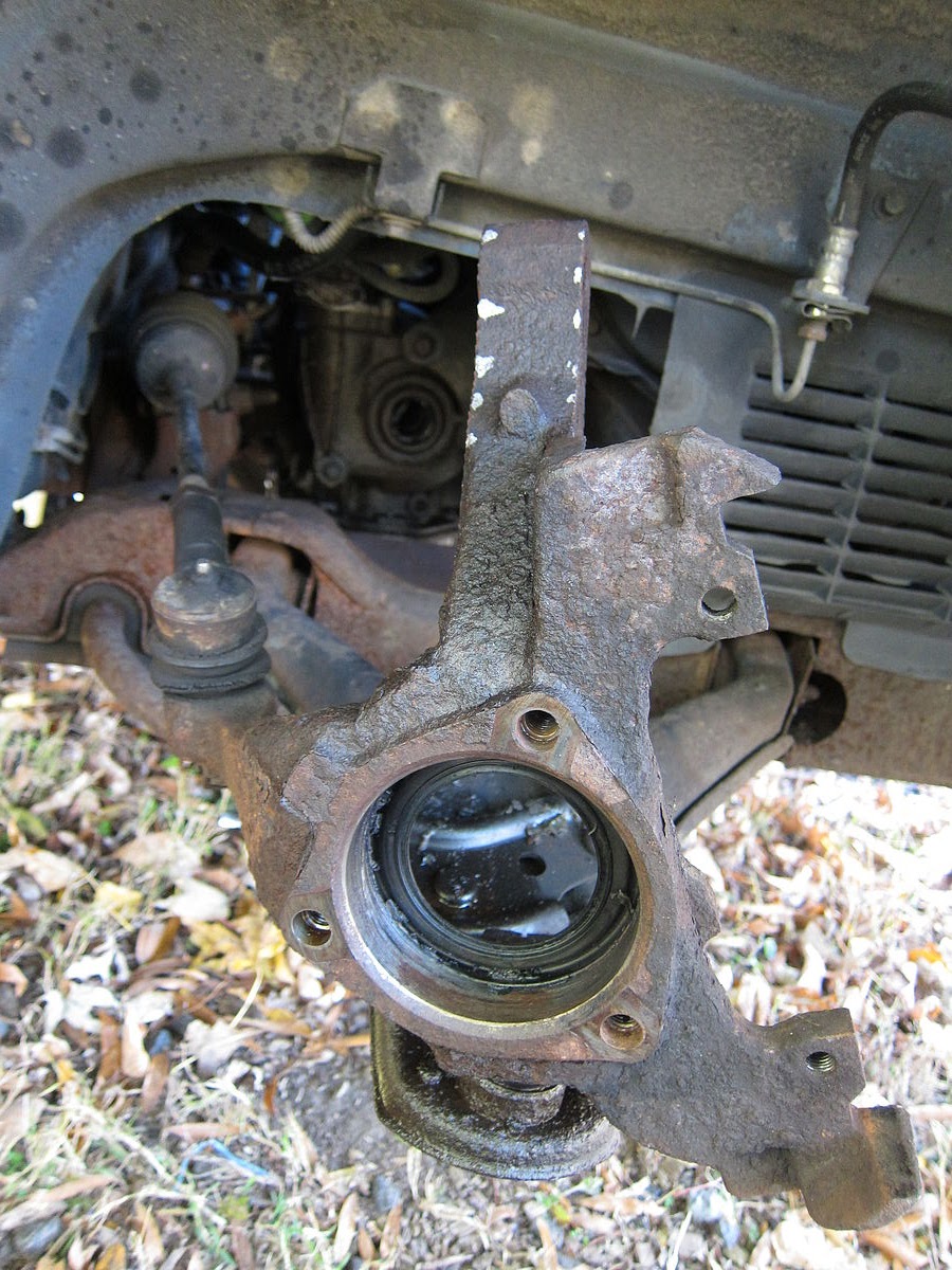
The wheel bearings are simple to remove on the Cutlass Ciera: They're held in by 3 star-drive bolts to the steering knuckle. No hydraulic press needed. The half-shafts came out of the bearings really easy. A half-hearted rap with the deadblow mallet broke them free.
Leaky tie rod ends: a project for another day.
The knuckle needs to be separated from the strut in order to pull the halfshaft out. I painted guidelines on the assembly so I could reinstall without throwing the alignment. The bolts holding the strut to the knuckle were fairly corroded, and a huge amount of work was required to break them free and unthread them.
The halfshaft is held onto a splined haft inside the transmission by a spring circlip. It takes a bit of force to pop it of. I ended up jacking the car up another few inches so I could put the breaker bar between the frame and the shaft housing, then hit it hard with the deadblow hammer. The housing looks like plastic, but is really cast aluminium, and it suffered no ill effect from the whack.
The exposed shaft in the transmission.
Getting the axle seal out of the transmission was not an easy job. Haynes called for a hammer and a cold chisel, but there is not enough room to get a good angle on the seal, or a good swing with the hammer, so the process of deforming the old seal required patience, several flatblade screwdrivers, and a needle nose vice grip. To get the seal out, I pulled little bits off until I could get between the seal and the transmission to really deform the seal casing. It took over an hour to finally dig it out.
Transmission without any seals. Drivers side, I believe.
Getting the new seal in was as hard as getting the old seal out. Finding a round object suitable to evenly push the seal in was not easy. I tried for another hour or two to use various scraps of PVC and the socket for the halfshaft nut, but the seal refused to go in flush. I eventually went to the hardware store and purchased a 2 foot piece of pipe that fit over the seal exactly. I also removed the strut to give myself a straight shot at the seal.
In the end, 10$ at the hardware store did in 10 minutes what I had spent several hours failing to accomplish.
Say hello to my little friend.
New seal, installed.
New and old halfshafts, compared. The new shaft slide right in and clicked into place without a lot of force.
Wheel bearing removed from knuckle. There is a dust seal on the back of the knuckle that matche a seal on the halfshaft. However, there is also a seal on the bearing itself. I still stuffed this with grease to keep anything from rusting together.
New wheel bearing.
Passenger side leaks, for posterity.
The passenger side halfshaft has a splined in the plugs into the transmission. I suppose it's impossible to put it together backwards, even if the different shaft lengths didn't give it away.
I pulled the bearing off the passenger side before removing the halfshaft to give myself more room to work. It only helps a bit, still a tight squeeze.
Installing the new shaft revealed that it came with a ABS sense ring. This oldsmobile doesn't have ABS, and, strangely, had a large iron ridge in the steering knuckle that almost seemed to exist to keep the ABS shaft from being installed correctly. The method of attachement for the abs ring wasn't readily apparent (glue? pressed? spotweld?) so I opted to grind of the ridge on the knuckle rather than try to remove the ring on the halfshaft.
After grinding, I had to clean up all the shavings to keep them from getting into the assembly. In retrospect, it took so much time to grind the knuckle that putting a notch in the ABS ring to see if it would easily come off would take a lot less time.
General notes:
-Every fastener seemed to be rusted together. This job could probably be done in less than 8 hours if nuts and bolts would spin freely.
-Paint guidelines on the interface between the struts and the knuckles to preserve the alignment.
-Remove the struts. It's just 3 nuts and it makes a lot more space in the wheel well.
-Jack up both sides of the car so it's easy to push/pull the rack without having to twist the steering wheel. Getting the end of the halfshaft out of the wheelbearing required a lot of experimentation to get the knuckle into just the right spot.
-Come prepared with lots of grease and threadloosening fluid
-Be patient and have lots of pointy tools for removing the axle seals in the transmission.
Some bygone aphorism stated that every journey starts with a step. In the case of half shaft replacement on a 24 year old car, that step requires a 36" long wrench and a 24" cheater bar. The axle nut was originally put on with Loctite and 190 ft-lbs. Then it had all of time and every weaving frost-heaved winter road in New Hampshire to rust over.
Marco Polo, eat your heart out.
The main inspiration for replacing the seals and and halfshafts is that they were all leaking. The shafts had been leaking for years, and though they still seemed good and tight, were in the way of replacing the seals that were leaking transmission fluid more quickly than I was comfortable with. I replaced the bearings too, since they are easiest to remove while the shafts are out, and the were getting a little chatting in hard curves.
The wheel bearings are simple to remove on the Cutlass Ciera: They're held in by 3 star-drive bolts to the steering knuckle. No hydraulic press needed. The half-shafts came out of the bearings really easy. A half-hearted rap with the deadblow mallet broke them free.
Leaky tie rod ends: a project for another day.
The knuckle needs to be separated from the strut in order to pull the halfshaft out. I painted guidelines on the assembly so I could reinstall without throwing the alignment. The bolts holding the strut to the knuckle were fairly corroded, and a huge amount of work was required to break them free and unthread them.
The halfshaft is held onto a splined haft inside the transmission by a spring circlip. It takes a bit of force to pop it of. I ended up jacking the car up another few inches so I could put the breaker bar between the frame and the shaft housing, then hit it hard with the deadblow hammer. The housing looks like plastic, but is really cast aluminium, and it suffered no ill effect from the whack.
The exposed shaft in the transmission.
Getting the axle seal out of the transmission was not an easy job. Haynes called for a hammer and a cold chisel, but there is not enough room to get a good angle on the seal, or a good swing with the hammer, so the process of deforming the old seal required patience, several flatblade screwdrivers, and a needle nose vice grip. To get the seal out, I pulled little bits off until I could get between the seal and the transmission to really deform the seal casing. It took over an hour to finally dig it out.
Transmission without any seals. Drivers side, I believe.
Getting the new seal in was as hard as getting the old seal out. Finding a round object suitable to evenly push the seal in was not easy. I tried for another hour or two to use various scraps of PVC and the socket for the halfshaft nut, but the seal refused to go in flush. I eventually went to the hardware store and purchased a 2 foot piece of pipe that fit over the seal exactly. I also removed the strut to give myself a straight shot at the seal.
In the end, 10$ at the hardware store did in 10 minutes what I had spent several hours failing to accomplish.
Say hello to my little friend.
New seal, installed.
New and old halfshafts, compared. The new shaft slide right in and clicked into place without a lot of force.
Wheel bearing removed from knuckle. There is a dust seal on the back of the knuckle that matche a seal on the halfshaft. However, there is also a seal on the bearing itself. I still stuffed this with grease to keep anything from rusting together.
New wheel bearing.
Passenger side leaks, for posterity.
The passenger side halfshaft has a splined in the plugs into the transmission. I suppose it's impossible to put it together backwards, even if the different shaft lengths didn't give it away.
I pulled the bearing off the passenger side before removing the halfshaft to give myself more room to work. It only helps a bit, still a tight squeeze.
Installing the new shaft revealed that it came with a ABS sense ring. This oldsmobile doesn't have ABS, and, strangely, had a large iron ridge in the steering knuckle that almost seemed to exist to keep the ABS shaft from being installed correctly. The method of attachement for the abs ring wasn't readily apparent (glue? pressed? spotweld?) so I opted to grind of the ridge on the knuckle rather than try to remove the ring on the halfshaft.
After grinding, I had to clean up all the shavings to keep them from getting into the assembly. In retrospect, it took so much time to grind the knuckle that putting a notch in the ABS ring to see if it would easily come off would take a lot less time.
General notes:
-Every fastener seemed to be rusted together. This job could probably be done in less than 8 hours if nuts and bolts would spin freely.
-Paint guidelines on the interface between the struts and the knuckles to preserve the alignment.
-Remove the struts. It's just 3 nuts and it makes a lot more space in the wheel well.
-Jack up both sides of the car so it's easy to push/pull the rack without having to twist the steering wheel. Getting the end of the halfshaft out of the wheelbearing required a lot of experimentation to get the knuckle into just the right spot.
-Come prepared with lots of grease and threadloosening fluid
-Be patient and have lots of pointy tools for removing the axle seals in the transmission.
Blinkenlichten II
Once taken, twice removed, I suppose.
By which, I mean to say that it was fairly certain that fixing the broken christmas light timer was possible if all the electrical components were intact. We bought two last winter, and thereby instantly removed the bedtime "Who's going to unplug the lights?" discussion and also the equally awkward "Wow look at the december electric bill!" associated with running the lights 24/7 during visits with family. On at 4:50, off at 11:00 every night.
Then, sometime this summer, one of the timers stopped working. Screen blank. No clicking relay. Zilch. Reset button did nothing. Plug/unplug did nothing. Appeared dead. But of course, I had already opened it and determined that it was almost too bloody simple to die. As long as the ballast capacitor stays in spec, it should work about forever.
I pried the timer open to see this again:
For reference, the left side PCB with all the components is an AC/DC converter, and an SSR driven by the transistor, which is in turn driven from the blue wire that leads to the right hand PCB, which is the timer microcontroller, the screen, and buttons (not shown). The major components on the timer board are few. On the back, there's a oscillator, a photoresitor ("Dusk"), and a battery (the green shrinkwrap thing). The timer charges from a 1.45 volt line through the red and yellow wires. I think the AC/DC conversion is actually 12 volts (for the relay), and then a seprate resistor drops it further to supply the controller. Though, that leaves the purpose of the big red capacitor unanswered. Regardless, I wasn't there to diagram circuits.
The controller battery was a) charging and b) charged. That narrowed the problem down to the controller and the screen. I removed the control board and noticed that one of the fingers that holds the screen to the timer PCB was loose. LCDs often use a silicon surface contact. I removed the screen and found the controller CPU underneath, along with test, reset, ISP and ground pads. I grounded the reset pad for 5 seconds cleaned the LCD contacts,and pressed it back together until it snapped. The screen started working, blinking time like a VCR.
Rock on green box, rock on.
By which, I mean to say that it was fairly certain that fixing the broken christmas light timer was possible if all the electrical components were intact. We bought two last winter, and thereby instantly removed the bedtime "Who's going to unplug the lights?" discussion and also the equally awkward "Wow look at the december electric bill!" associated with running the lights 24/7 during visits with family. On at 4:50, off at 11:00 every night.
Then, sometime this summer, one of the timers stopped working. Screen blank. No clicking relay. Zilch. Reset button did nothing. Plug/unplug did nothing. Appeared dead. But of course, I had already opened it and determined that it was almost too bloody simple to die. As long as the ballast capacitor stays in spec, it should work about forever.
I pried the timer open to see this again:
The controller battery was a) charging and b) charged. That narrowed the problem down to the controller and the screen. I removed the control board and noticed that one of the fingers that holds the screen to the timer PCB was loose. LCDs often use a silicon surface contact. I removed the screen and found the controller CPU underneath, along with test, reset, ISP and ground pads. I grounded the reset pad for 5 seconds cleaned the LCD contacts,and pressed it back together until it snapped. The screen started working, blinking time like a VCR.
Rock on green box, rock on.
Friday, November 22, 2013
Pop Goes the Breaker
The breaker blew.
Not for the first time.
The lab was silent as all the pumps, computers, heaters, and devices on the north wall went dark.
My frustration drove me to reset the breaker to get the ball rolling again. The pile of shit to do was high and the tolerance for failure low. Then, I realized something: every time the breaker had blown previously, I moved things to different outlets to distribute the load between other breakers. The bench had outlets labeled #2, #4, #6 and even a few #7 and #8s. Why were they now dead too? Shouldn't it only be outlets of a common number?
I turned off some pumps and went to the electrical box. Breaker #2 was warm and popped. #4 and #6 were stone cold and in the on position.
The outlets in the lab were mislabelled.
A thermograph showed that only a few breakers were carrying any load at all, with #2 getting the brunt of the use, probably overloaded.
Time to call an electrician.
Not for the first time.
The lab was silent as all the pumps, computers, heaters, and devices on the north wall went dark.
My frustration drove me to reset the breaker to get the ball rolling again. The pile of shit to do was high and the tolerance for failure low. Then, I realized something: every time the breaker had blown previously, I moved things to different outlets to distribute the load between other breakers. The bench had outlets labeled #2, #4, #6 and even a few #7 and #8s. Why were they now dead too? Shouldn't it only be outlets of a common number?
I turned off some pumps and went to the electrical box. Breaker #2 was warm and popped. #4 and #6 were stone cold and in the on position.
The outlets in the lab were mislabelled.
A thermograph showed that only a few breakers were carrying any load at all, with #2 getting the brunt of the use, probably overloaded.
Time to call an electrician.
Wednesday, November 20, 2013
Subscribe to:
Posts (Atom)