Mountains

Mountains
Showing posts with label Dear John Life is Boring. Show all posts

Thursday, August 10, 2023

Dell Laser Mouse (M-UAV-DEL8) Repair Notes

I used a cheap and fairly commonly available Dell Laser Mouse (M-UAV-DEL8) for many years, and really liked it, as it provided all the features I wanted in more expensive mice (laser tracking, decent response, on-mouse tracking adjustment, and a scroll wheel with some buttons in places I could manage. I had two over time.

Over time the quality of the tracking started to deteriorate and the mice eventually became essentially unusable. Cleaning the lens under the mouse and applying compressed air or suction from a vacuum cleaner didn't improve the performance. I assumed that whatever cheap sensor or other electronics in the mouse were dead and I purchased a new mouse and the Dells went into the junk pile.

Years later, i wondered what was up and decided to open the mice for cleaning. It turns out that the optics sit on a wide piece of clear plastic and it catches dust and debris from the top of the mouse, but this is very difficult to remove without taking the mice apart. Cleaning the sensor brought it back to full performance. I also cleaned the scum from scroll wheel mechanism and inspected the click-switches.

Repair notes: 

Disassembly: 

The mouse comes apart easily. There are 2 Phillips screws under the rear skate pad. The rear pad can be removed non-destructively with knife and replaced.


 After removing the screws the mouse has two circuit boards connected with thick ribbon cables. These boards are on both halves of the mouse. You can remove the top board from the mouse by moving it left and right relative to the bottom and removing the two retention screws. 


The bottom circuit board has the side click buttons in the way. The buttons can be removed with a thin prying object like a knife or small screwdriver by prying the retention tabs inward and pulling up on the buttons.



After that, there are 2 screws in the bottom circuit board and the electronics and scroll wheel will just slide out.


Laser Optics/Lens:

To remove the lens from the bottom for cleaning, there are two small tabs that are melted into blobs on top of the laser sensor. Cut the tabs with a knife and the lenses will fall away. You can clean it with a paper towel and isopropanol. I noticed that you can see the dirt on the optics with the white towel behind it... this makes getting it clean easy... it took more than a few wipes to get it spotless.

I reattached the lens by putting 2 small dabs of hot glue on the outside fingers of the lens that go on the outside of the laser sensor.


 In the photo below you can see the big air gaps around the laser sensor, and the big lens tray that collects material that falls on it and prevents cleaning from the outside.


Scroll wheel:

I would call this a second generation scroll wheel: it has a stub that goes into a mechanism that sends pulses when scrolled and supplies the rotating resistance. You can pull the wheel out of the mechanism for cleaning.  There is a spring that provides the resistance for the scroll wheel click mechanism that is on the other end of the shaft, this catches on two small towers over the scroll wheel click switch. (I thought it was supposed to slide between the towers, but assembled this way it becomes obvious that is not correct).

Mouse click switches:

In the mouse that I paid attention to, these are Omron D2FC switches. They are through hole, so if double click issues showed up, they could be replaced. You can also attempt to repair the switch mechanism. The tops of the switches pop off by gently prying the small retention tabs of each side of the switch (be careful not to loose the small white actuator inside). I cleaned the contacts but did not attempt any spring bending. I measured the switching voltage, it's 5V, so I think they will go for a very long time.

Weights:

I removed the weights from the mice. They are held in by a single screw. At some point, a mouse is too light for me, but my preferences have moved away from heavy input devices over time.


Design notes:

To my surprise, these were made by Logitech for Dell. While I think they are somewhat unique, they have a BOM and design. (single sided PCB with through hole parts and very limited complexity) that is typical for a cheap 2000's mouse, but the core microcontroller and laser sensor are on par with some nicer mice in the era.


The mouse microcontroller is a Cypress CY7C64823 (Datasheet: https://www.infineon.com/dgdl/Infineon-CY7C63310_CY7C638xx_enCoRe_II_Low_Speed_USB_Peripheral_Controller-DataSheet-v21_00-EN.pdf?fileId=8ac78c8c7d0d8da4017d0ecc994f46c9). Nothing fancy, but it's interesting to see from the datasheet that Cypress has software that lets you basically build the mouse/input device characteristics from their library. I wildly guess it's running between 12 and 24 mhz. It can also support both low speed USB and full speed USB-2. It has 256 bytes of memory and 8 kilobytes of program storage (flash). This is a 24 pin surface mount device that I think could run directly from the ~5V USB bus with little power conditioning. I regret not following the traces, I wonder if it is using all the GPIOs? 8 button functions (Left, right, forward, back, scroll up, scroll down, scroll button, resolution), the USB bus (2 pins), and an SPI connection to the laser sensor make that seem unlikely.

The optical sensor is an Avago ADNS-7550 (Datasheet https://datasheetspdf.com/pdf-file/913766/AVAGO/ADNS-7550/1)  Notably the sensor features the same 400/800/1200/1600 DPI that matches the dell and logitech literature, as well as a 2000 DPI mode that isn't used by the mouse. I didn't track traces, but from the spec sheet, it looks like a minimum implimentation is an SPI connection to the micro controller, along with an interrupt line from the mouse to tell the controller there is activity, and then connections to 5V power from the USB bus.

The spec sheet has some interesting charts showing how the sensor acts on different surfaces.

Mine were made around 2008 or 2009 according to the date code.

It looks like, between the two mice, there were several revisions to the circuit board over time based on the revision numbers printed on the silk screen.


Tuesday, May 1, 2018

Oldsmobile Cutlass Cierra/GM 2.5L I4 TBI - Won't Start Hot Troubleshooting 2: DIS and Crank Sensor

My 1990 Olds Cutlass Ciera with a GM TBI 2.5 L I4 Iron Duke would periodically not restart after it had run for a while and was hot. The situation reached peak hilarity when it failed in my carpooling coworkers driveway on a cold morning.

The initial attempt at troubleshooting focused on the TBI unit and fuel system. The next likely point of failure was the coils/DIS (Digital Ignition System [module]), and crank sensor. On the GM 700 Series TBI system, these components are directly connected together into a single unit.

There's a decent write up on the system on the Megasquirt Page. Between that page and the Haynes manual, I've been able to construct a diagram that looks about right, but I haven't really tried to track down every single pin on the DIS (I think there's a separate tachometer output, and I neglected fuses, coils, and the fuel pump circuit.


While I am still a bit unclear on the specifics of the operation, the inductive pickup crankshaft sensor is directly connected to the DIS, which then sends pulses to the ECU (Purple/White Wire). The ECU then uses a lookup table determine when to fire the spark plugs and sends a pulse back to the DIS to trigger a spark (White Wire). The system is a 2 coil, waste spark system, so each cylinder ends up sparking twice per cycle.

The ECU also uses the pulses from the crank sensor to time the fuel injector by grounding the injector (Dk. Blue wire). No injector pulses mean no fuel, which would lead to the condition observed that the car didn't smell very gassy when it wasn't starting, and it wasn't stumbling or coughing. This could be caused by the DIS not getting a signal from the crank sensor, or by the DIS going on the fritz and not sending a signal, or by a wiring failure.

Also of note, during startup, the DIS completely controls spark, and the ECU grounds EST bypass. Once the engine is running, the ECU sets ECU bypass to +5V, and sends an EST signal.


Checking the coil/DIS/crank module is not an easy task on this car. GM thought it was so reliable (ok, lets face it, 28 years is a good haul) that it put it in between the engine and the fire wall, above the rack and frame member, and below the TBI and intake manifold, and then obscured every access route with cables and tubing. It's a good job for someone with a good spacial sense and skinny arms.

To check the ignition module, a lot of stuff has to come off the top of the engine.

I bought a fuel line disconnect tool kit from amazon. Annoyingly, it turns out there really aren't that many different types of fuel lines, the kit comes with essentially 4-5 different versions of the same tool. For this engine, only 3/8 and 5/16 tools are needed.


I left a rag to soak up the fuel that dribbled out of the fuel lines.

Air filter off, and throttle cable and crank held out of the way with a bungie cord.


There are 4 nut holding the DIS on to the this alumnium tray, with captive bolts. The tray isn't very thick, so the bolts will start spinning as the nuts are loosened, There are 3 bolts holding the whole assembly to the block. The small two pin connector on the bottom of the tray is from the crank position sensor.

After removing the 3 big bolts, I tried to pull the sensor out in one piece. Instead, it handily snapped in two. Drat.

After many hours of fiddling with different tools, I was able to drill the back of the inductive pickup with small cordless drill and insert a screw, which allowed me to pull the crank sensor out of the block. I nearly gave up and dropped the oil pan to push the sensor out from the inside. The sensor body was heavily cracked and it's magnetic character had accumulated a fine coating of metal shavings.

Cleaned up, the cracks are a lot more apparent. This looks like the point of failure!

The inductive pickup end. Very magnetic still.

I then went about reassembling the DIS system with new parts. I bought a Standard Motor Products LX344 DIS and PC3 crank sensor. The sales literature claims the LX344 is an improvement over the Delphi/GM module, though I can't quite imagine how it could improve.

The crank position sensor bolted to the aluminum heat spreader. The socket gets a thick bead of PTFE grease.

Comparison of the Delphi (top) and Standard Motor Products DIS. Outwardly, they're almost identical. I assume the Delphi didn't come from he factory with spider parts.

The LX344 came with an extremely useful troubleshooting guide! The guide explained that the DIS I was about to replace was probably not faulty, and that the ECU, the coil pack, and the crank sensor were likely culprits! To check the ECU, it suggested monitoring the RPM line from the DIS and the EST return for pulses. To check the coils, it suggest checking for spark by direct test or switching the coils around. It suggests checking the crank sensor resistance and for damage to it's housing. I guess that's what I found.

I decided to not replace the original GM coil packs, although when I was ordering the DIS and sensor, they were tempting given the effort involved. They looked ok and ignition hasn't been an issue.


The reassembled DIS/coil module. DON'T DO THIS! It won't fit into the car unless you take the crank sensor off first. The crank sensor has to be attached once the unit is under the intake manifold.

Here's what the DIS/crank sensor hole looks like through the top of the intake. Basically one stands on hands and knees over the engine and reaches down with the right hand to wrench. Fortunately, the space under the intake is quite voluminous, and it's possible to fit a work light and other things and there's room.

Closeup of the crank sensor hole. I put a thick gob of grease there, in the hopes if someone ever has to pull the sensor again, it will just slide out.

I took the chance to re-route the spark plug cables as GM intended.

After the replacement, which took all weekend thanks to the broken crank sensor, the car started right up and has not failed since.

Saturday, October 14, 2017

Wednesday, December 9, 2015

Need more Crass Bypass Gas: Iron Duke EGR Valve Swap

Or

The ChevOldsmobuiac's EGR valve finally died in a way that surprised me.

The majority of the A-body oldsmobile cutlass cieras on the road are demotivated by 4-cylinder Iron Duke engines.  The upshot is that the engine is shared with many other GM vehicles, including the S-10, Fiero, and of course, the Grumman LLV that your postman probably dreads driving at work every day, so there is a lot of information available about the care, feeding, and repair of the powerplant, even though there are many production line tweaks that can make swapping major components (heads chief among them) difficult if researched first.

The Haynes manual notes that the EGR Valves tend get carboned up and sieze. Part of my regular maintenance has been depressing the diaphram to ensure that the valve could actuate.
 
A few months ago, the Check Engine light started coming on after the engine warmed up (it seemed like after 15-30 minutes of operation... I could almost pick the intersection after a week of commuting), after the light went on, the engine would noticeably ping/rattle under moderate acceleration. While I initially suspected another faulty ECM module, reading the codes yielded a consistent bad EGR valve code (Code 44 also for lean exhaust).


Low and behold, with the engine at idle, the valve was fully closed, as could be felt on the back of the diaphram with engine air filter off.

Of note, the EGR valve on this car is completely mechanical: it is connected directly to the intake manifold and it is regulated by a pinhole orifice on the EGR valve body. It slowly opens and closes as engine vacuum changes: under idle, moderate accelleration, and coast, it is open. Under heavy load, it closes.


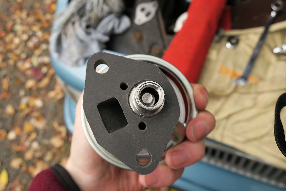
Detailed photos of the new valve:
The diaphram appears to be a silicone membrane.

Pinhole that regulates gas flow to the intake manifold.

Serial Number.

Exhaust goes into the round orifice and out the square one.

Closed position.

Open position. When you open the valve, the cover the vacuum nipple, it should stay open. Otherwise, there's a leak in the diaphragm.

The box it came in. Recognize the part number?

Old EGR valve exposed under the air filter snorkel. I should have covered the TBI, but I was on crutches with I did this operation, and wasn't interested in making a lot of trips.

Old EGR Valve. Interesting: Old part number does not match the new one. Hope this works.

Carboned up old valve.

I'm totally guilty of smearing a bit of antisieze on the port the last time I took off the EGR valve, because it was corroded on pretty well.

 Vacuum test the new valve one more time. It's kind fun, after all.

Side by comparison. Note: Hecho en Chine. I feel a little bad for whoever made the new valve, since they will probably never see any car that it is designed for. Then again, maybe I should feel happy for them, since all the cars they will see were made in this century.

Bottoms looks pretty similiar. Gasket is stuck on the old valve.


The swap was pretty trivial. It took about 10 minutes with a couple of different 13 mm wrenches to reach under the diaphram and navigate all the hardware on the top of the engine. I highly recommend a deep-offset 12 point, 13-mm wrench for this job. A flex head ratcheting gear wrench might also work, but I didn't have one to test. For completely visible bolts, they were awfully obscured.  With plain wrenches, you might have to disconnect the throttle cables to get enough swing to get the bolts out. This is not a good party for your socket set.

While you're at it, I suggest replacing the now very rusty bolts with new ones and putting a dab of antisieze on them. What possesses car makers to put iron bolts in aluminium parts is beyond me, and is certainly a sign that large portions of our engineering population failed basic chemistry.

In the end, the engine appears to be a lot happier. For a long time there's been a lingering burble/valve rattle sound that I now realize must of been pinging due to lean mixture. That sound is now completely gone. This engine does not have a ping detector, so this might be worth looking at if you have mysterious pinging. The EGR valve had to be very dead for the computer to turn on the check engine light.

Another note is that this probably means that you can't put a plate over the EGR valve on fuel injected engines without remapping the ECU to accept and adjust the mixture. I'm not sure how exactly the car knows the exhaust gas is missing from the mixture, but I'll be it has to do with a combination of manifold pressure and the position of the idle air control valve. Long story short: unless you know how to remap an ECU, getting a blockoff plate will not help you on the TBI engines. Since my EGR was failed in the closed position, it was functionally the same as a block off, and the computer remained unhappy and drivability was compromised by excess pinging.


Auto Parts Epiphany

I'm beginning to think, nay, truely believe, that most replacement car parts, even OEM replacement parts, are inferior to the components originally installed on the car.

The immediate case in point is the parking brake cables on the ChevOldsmoBuiac, my 1990 GM a-body oldsmobile. The original cable worked perfectly for 20 years, though it eventually seized, piece by piece (it has 3 sections), over the past 5. A few years ago I replaced the last piece and thought I was good forever.

These cables seize because the outer sheathing coils rust and expand, constricting the nylon coated inside. The new cables apparently had inferior environmental protection, and so now have suddenly decided that they can barely budge.

Similiarly, the original brake cylinders (rear) and brake calipers (front) have required periodic replacement due to leaks and seizing every few years since the originals were replaced in 2007 or so. If memory serves, we're on the third set.

We also blow through rear pipes and mufflers at a rate of one ever 3 years. It's kinda nuts.

Far cheaper than a car payment, since I'm doing the work, but still kinda nuts.

I don't think this holds across the board, of course, I swapped the OEM shocks and struts in the Olds for Monroes in 2005 and they've been great. I only am thinking about replacing them now due to dry rotting bushings and the impressive amount of rust present.

Perhaps a descerning shade tree mechanic would do well to attempt to source and install only premium parts.

Except I mostly do that, and it doesn't seem to help.

Monday, June 30, 2014

Overkill

I decided to use 7$ in parts to fix a 13 year old, 20$ tire pump. The old tire stem gave up on the idea of attaching to the stem without leaking (and often without really attaching).

The rationale being that after the itself pump died, I could cut the 7$ part off and use it elsewhere.

Somewhat annoyingly, this is exactly the kind of part that is not available at home despot. That problem has been striking a lot, and it makes me consider their product selection mentality. The store seemed designed for me to spend 20-$500 on an motorized tire inflator of some stripe. Luckily, the autozone nearby had exactly what I was looking for.

Sunday, June 8, 2014

Woodpecker Frustration

When you hear woodpeckers drilling at your house, you know you have at least one problem: woodpeckers. The ruin your morning coffee experience with loud chirping and staccato jack hammer noises that resonate in the walls of your precious craftsman style bungalow that you're signing away half your monthly salary just to live in. If woodpeckers are on your list of awful things in life beside Yugos, bears, LISP, burnt eggs, and children, they really should be. You will feel more complete knowing you have a full list of things to intensely dislike.

Another important point about woodpeckers is that they are usually just there because there is something else that is very wrong and annoying you that you just don't know about yet. It is highly likely that the thing that is drawing the woodpeckers is also a problem, and often is the root of your pecker frustrations.

For example: this was the root of my woodpecker frustrations: rotten trim.


Looks lovely, doesn't it? The wood peckers, arriving on springs coat tales, were having a blast boring in to it, plucking out great pieces of fibreglass, and chirping up a storm.

If anyone in town finds random bits of fibreglass around it wasn't us, I swear.

When we first bought the house, there were pronounced problems with trees touching and growing into it. A high priority was cutting them back, but the damage was still done, and much of the trim has large holes worn in it. Additionally, I found that the gutter on that part of the house wasn't flashed correctly, so water drained behind it, across the trim, instead of into it. Note: the drip edge terminates in the gutter!

Tired of constant pecking, I crowbarred off the offending bits, inspected the damange, then stapled heavy plastic over the problem while I contemplatd what to do.

Gutter removal. Aluminium gutters are quite light. The major problem is getting behind the nail head to pull them off.


A blownout picture: at least the ends of the rafters are not rotted,and the decking is in great shape.

You can seen where an old squirrel nest used to be on the left. Center are the supports I made for holding the new trimwork to the rafters. They held each piece of trim in place while I aligned and screwed them in.


New trim boards. These are made of PVC and should never rot. Because my car can only handle 8 foot boards, I had to use two pieces for everything, which complicated the project. That and the cellar door.

Replacement cleat. It's really tough doing a good job creating a new cleat. It's very tough to work out where to install it on the wall. The geometry is simple. The requisite measurements standing on a ladder are not. And the brick wall is bowed. Thus, I'm pretty sure that the horizontal parts are not quite planer. You won't notice, right?

Offsets installed to hold the horizontals

Another view of the offsets.

Horizontals installed. The bowed wall meant that the sides of the 1x12s had to be shaved and cut (as much as 2 inches in places) to fit. Any residual gaps got caulked.

Another view. The outside corner ended up being the summation of all the offsize cuts and rounding errors.There's an extension off the cleat for the inside trim at the end of the house (the darker wood). There's also a small panel where the combination of the 1x12s (which were 6' long) didn't quite reach. Did I say "thank goodness for caulk" yet? If not, I should.

Thank goodness for caulk.


All buttoned up and read for caulk and paint.


Painted and caulked.

See! I told you it would look great.


Gutter reinstalled.

If I had to do it again, I would have done a few things differently:
  1. I would have spent the money for PVC all the way around. After I found out how easy it was to work with, and really got into the pain of fiddling with the ladders around the cellar hatch, I determined that never having to work there again would be great and high durability PVC would help.
  2. Sand all boards before installation and use primer before painting, the fit and finish will be way better.
  3. Consider full length pieces wherever possible. It means fewer measure/cut processes and it just looks better without seams. 
  4. Next time, when in the hardware store holding the big crowbar, thinking "this will make getting that gutter/trim/board/nail/woodpecker out", i'm going to buy the godamn bar, put it in the car, drive home, and wreck things. I'm not going to poke around with a hammer, a small prybar, and a iron pike for 3 hours.