Mountains

Mountains

Thursday, February 27, 2020

Converting my Old Laptop into Desktop All-In-One

or, "reddit.com/r/buildapc, eat your heart out"


In 2011 I purchased an Lenovo x120e netbook, which I used for couch internet, travel, and periodically logging GPS data from my lawn tractor.

Powered by an 1.6 ghz AMD E-350, with 4 gigabytes (and later upgraded 8) of DDR-3 ram (sadly on single channel), and a 7200 RPM hard drive, RealTek RTL8192 (or maybe 8188) 802.11n 1x1 2.4 ghz nic. It was both faster than the T42 I replaced it with and slower than contemporary full laptops (it was about 1/5th the speed of an 2011 i7 Macbook pro). Over time I replaced the battery, upgraded from Windows 7 to Windows 10, spilled a few beers on it, replaced the cooling fan, and switched to Ubuntu. It was perfectly adequate for the 2011 internet and the Radeon 6350 graphics made H.264 video and indy games great, but by 2016 it was feeling sorely underpowered, and in mid 2019 the battery was kaput, the cooling fan was buzzy, the speakers were shot, and I avoided using it online because any Web 2.0 content was a recipe for misery.


I relegated it to a drawer and bought a cheap refurb i5 dell corporate machine that is, frankly, miles better.
The X120e, at a point in time where it was still fast enough to be useful

I was waiting for a chance to recycle it, when I stumbled upon a LifeHacker where someone converted an old laptop into a workbench All-In-One (AIO). My x120e was in far worse conditions, but I knew the screen and motherboard worked, and I had an old SSD that would be a worthwhile upgrade to the spinning drive.

My motivations for this project were:
  • I prefer a mouse and keyboard for any kind of serious computing activity
  • I had stuff laying around doing nothing
  • It seemed fun to try

A major challenge for the construction would be to replace the stock CPU fan with something else I had in laying around. I have a decent collection of old computer fans and a few heat sinks, so I had high hopes to make something work.

I carefully took the laptop completely apart, as it would not be possible to mount an alternative cooling system in the chassis. I then tried different combinations of heat sinks and fans with different orientations of the motherboard behind the display. This computer runs just fine without a battery, and 9 cell battery with a 30 second run time is comically useless. so I wrapped the battery terminal on the motherboard with electrical tape, secured with a dab of hot glue, and set aside the battery for recycling.

The good news was that the display cable was long enough to support the motherboard being oriented with the cpu facing either towards the display or towards the back of the computer. However, I found it challenging to mount any of the heat sinks I had: they were all huge and the motherboard mounting brackets were not well placed.

CPU overwhelmed by a big heat sink. Note that it is touching the components.


I tried to shim the CPU with piece of polished aluminum to lift the heat sink off, but it didn't solve the mounting problem.

I ultimately decided to try a low effort solution. The e350 is rated at a mere 35w TDP, which seemed like overkill for even smallest desktop CPU heat sink I had. so I though that instead of trying to replace the whole heat sink, I could maybe just put a fan directly on the stock heat pipe and heat sink and treat the whole assembly as a heat sink.
The stock heat sink and cooler, with worn out fan attached.
With the fan removed, it was obvious that some cleaning would be needed.

I soldered the JST connector from the original cooling fan to a 120mm fan I had in the parts pile. While the 120mm fan is designed to work at 12V, it spins well at 5V and pulls less current than the stock fan. I elected to mount it so it blows outwards to the back of the case.

I made enclosure out of twin-wall polycarbonate (i.e. correlated plastic). I had a bunch from a prior project, and it is extremely easy to cut with a knife and hot glue sticks to it well.

I mocked up how I wanted to mount everything, then started cutting and gluing pieces of twin-wall. The fan was offset off the back of the display with shims.


Tabs with slots were used as legs to hold the motherboard to the back of the display. This way the fan has maximum coverage of the heat sink.

The original drive tray was kept as a drive support, and wings were attached to support the sides of the case. A baffle was also added to help keep the fan from recirculating warm.
 

 Another problem that removing the motherboard from the laptop presented was how to turn on and off the computer. The power button was molded into the base of the laptop, and the connector was a ribbon cable. I tried using the power button PCB, but the button alone felt fragile.
 

Instead, i cut the power button from the enclosure and glued it to the front of the display with a rear twin-wall support to keep it from snapping when pressed.


The power symbol is upside down, but it works.

Before putting the back on, I made sure to anchor all the wires (often foil shielded) with dabs of hot glue and electrical tape to keep them from getting free and either shorting out and causing trouble.

A quick test showed a happy computer with an external mouse and keyboard.


I added some holes to the back and bottom of the case, and a couple of flaps held together with duct tape for hard drive and VGA access.

I decided to return the machine to Windows 10, as it has the best driver support for the graphics card, with it's AMD VCE 3 h.264 decoder, and I wanted to have a decent experience watching videos in the workshop. As I had updated the Windows 7 installation to Windows 10 previously, microsoft recognized the machine and installation was quick and largely painless. I did download the latest drivers from AMD and Lenovo. The only snag I hit was that the Realtek RTL 8818 wireless card would not connect to our new wireless router. This wasn't surprising, as the wireless performance of the machine had always been bad (at points, we actually suspected it to be so bad that it was slowing down other machines on the network). However, no combination of RTL-8192 (or 8188) drivers or settings I tried would yield it detecting our 802.11AX router. From what I read, Realtek never got a working driver set for it. I eventually bought the bargain TP-Link T2u-plus recommended by wirecutter, which thankfully did work out of the box, though it worked a lot better with the TP-Link Drivers vs the stock drivers from Windows Update. That brought the total cost of the project to something like $17.


Frankly, the quality of the connection with the new wireless card does not seem any better than the old one. While the Windows claims a high speed connection to the router, internet speed tests show the x120 can only handle internet browsing at around 10 megabits, and copying files to and from the file server is limited to around 200 megabits. Both scenarios appear to be bottlenecked by the CPU, which goes to 100% in the task manager at the slightest provocation.

In order to get decent video playback performance, I installed chrome with the h264ify plugin.


To hold the machine upright, I used an old cookbook holder that was gathering dust.

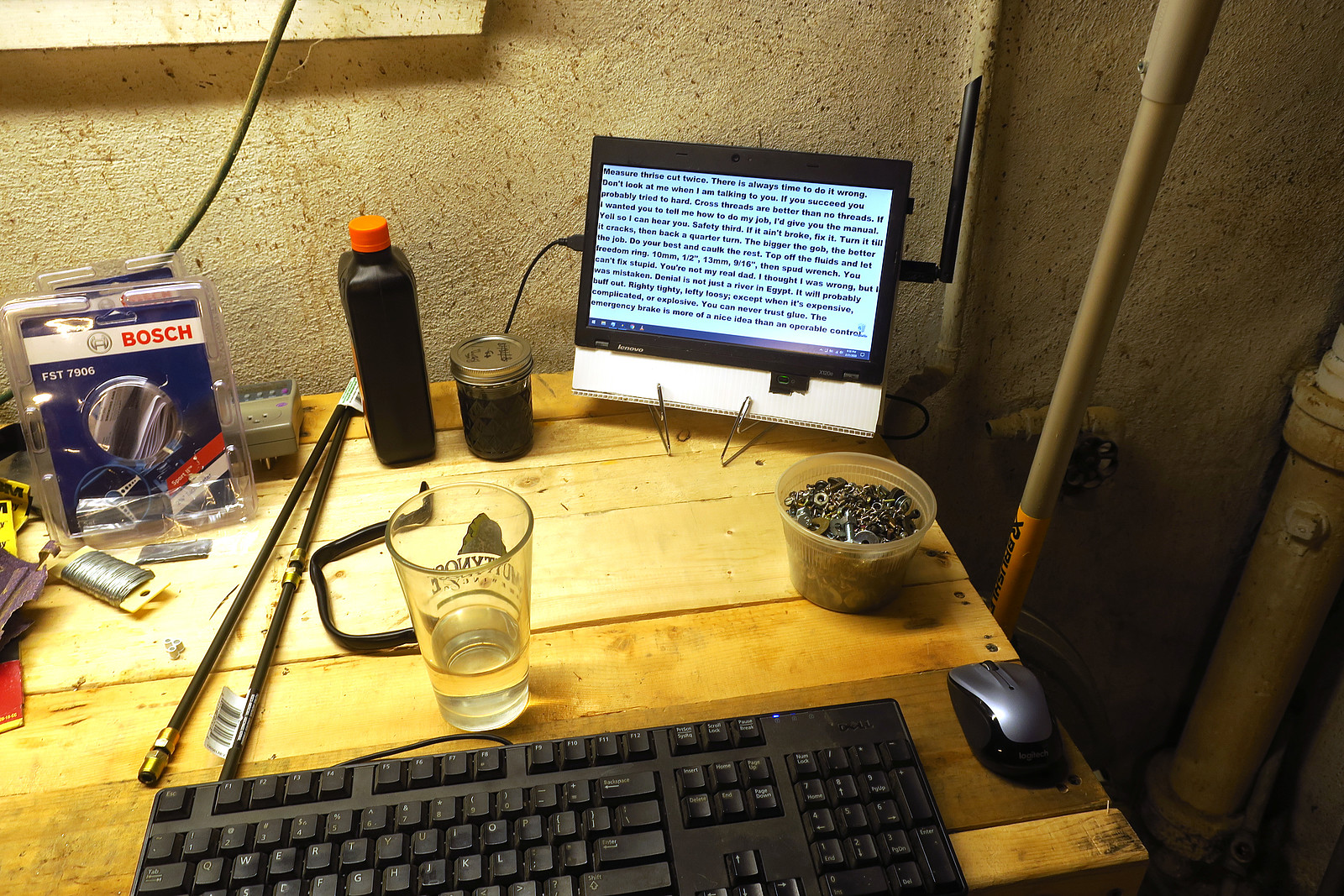
Behold, the workshop computer.
To test the stability of the system, in installed BOINC and Seti@Home. After an hour of running 2 CPU+1 GPU work units, the enclosure becomes slightly warm, but the machine is stable and most of warm air is leaving through the heat sink, so the fan design is functional, though not "ice cold". (Though, I have never felt the x120e was a cold running computer, like many users it's always somewhere between warm and very warm).

If I ever take the box apart (the irony of going full apple and building a PC with glue not screws is not lost on me), I'd take another crack at the cooling solution: I realized that the original copper cooler could be soldered or brazed to a larger piece of copper or aluminum, thus solving the mounting and size problems I encountered trying to attach desktop style heat sinks.

My major complaint was that I didn't not find a way to build speakers into the machine. I'll have to attach something externally via the 3.5" jack.

Also, I was surprised by the time it took to build the box: it took almost a full day to dissasemble the laptop, figure out how to orient all the parts (screen, motherboard, power button, USB, power, and vga ports, then somewhat carefully measure, cut, and hot glue twin-wall pieces until the unit not longer looked and felt like a cereal box full of wires and circuit boards. I certainly would NOT recommend buying an old computer for this: just get a raspberry pi or used PC if you are starting from nothing.


Saturday, February 22, 2020

My Rambling Thoughts on Using a Snowblower with a Lawn Tractor

When I was looking at options for removing snow from my long driveway and sidewalks, I found out that many lawn, garden, and other small tractors can be fitted with a snowblower. However, I was frustrated that there wasn't a lot of discussion online in forums and blogs about owners long term experience moving snow this way. Having used this for several years, it seems like an appropriate time to write about this.

Background

I live on a flat property with a densely packed gravel driveway, paved roads, and sidewalks on gentle grades. I ultimately got a well used Craftsman tractor (ca. 1998) with a 19.5 HP briggs twin and a Craftsman branded 40" agrifab snowblower (Craftsman Model No. 486.24839), along with a ~50 lb barrel weight in a tray on the back to improve traction. I added a lugg handles kit and bolted an 50 lb disk weight (from craigslist) to each wheel, and a generic set of ATV tire chains for added traction.


My Experience

In a word: size

The major difference between using a lawn/garden tractor tractor and a walk behind snow blower is the length.

While it is pretty easy to spin a walk-behind blower in place, or simply walk it backwards in it's track, in all but the most shallow of snows, the tractor has two directions: blow forward or reverse in it's cleared track. Because the center of mass is not over the drive wheels, turning the tractor around to reverse the direction of snow removal is practically impossible in any snow that is worth attacking with the blower, as it will get mired.

When sharp turns must be made, a space has to be cleared so that the wheels can find purchase. For example, when clearing a side walk, the 90 degree intersection at a street corner cannot be navigated simply by turning the tractor in one smooth motion. Instead, the machine needs to be backed about 1 tractor length, cocked at an angle in the direction of turn desired to shave off a side of the snow bank, the moved forward until the blower is over the adjacent walk. This is repeated until the machine can make the turn, often require a huge amount of snow to be removed in the area between the two directions.

As mentioned before, the center of gravity is not well located for moving snow. The blower weighs north of 100 lbs (50 kgs), and is cantilevered over the front steering axle, counterweighted by the engine, driver, wheel weights, and barrel weight. This means that:
  1. The front axle is always carrying a huge load, and that the steering gear is constantly stressed from steering the wheels with extra friction against the ground. 
  2. It takes considerable extra weight on the rear drive wheels for them to be effective, as the blower gives the unit a tendency to pitch forward. 
  3. When the blower is lowered, the situation is reversed, and the drive wheels pushing forward against the blower cause reduced weight over the steering gear, reducing steering forces while moving forward with the blower engaged.
As such, the operator needs to avoid situations that would require them to reverse up hill, as the least amount of traction is available under those conditions. Tractor using a snow blade are more able to cope with hills because the blade doesn't weigh as much, so there is more weight over the drive wheels, and they are shorter, and thus beating a hole big enough to turn the machine around in is a more viable possibility.


The fully equipped tractor is about 80" long and a bit more than 40" wide. The tractor has 60 lbs (25kg) of sand and scrap iron in the rear barrel and two 50 lb (20 kg) weights on lugg handles on the wheels for a total rear weight addition of 160lbs (~65 kg).
Aside from the poor maneuverability, the tractor/blower combination is generally less exhausting than a walk behind or a tractor/atv with a plow. The machine is carrying the seated operator, and the operator doesn't have to constantly lift, yank, and pull the unit to change direction, and there isn't the jarring that one experiences ramming into snowbanks with the plow at speed. In contast the tractor operation requires a good bit of concentration to manage the rate of forward travel, the direction of travel, and the angle and direction of the discharge chute, which are spread over 5 controls while the operator has one foot and two hands to manage them with.


 Required Engine Power

It seems like the 19.5 briggs twin is more than capable of driving the 40" blower. My determination of this is that in deep (>12") snow, the limiting factor in rate of travel was the ability for the tractor to feed snow from the first impeller stage into the second stage of the unit. The tractor would start pushing snow forward and start burning belts, but the engine would never stall or bog down. I surmise that engines with ratings better than 16 hp are probably capable of driving blowers up to around 50" with acceptable results. As far as I can tell the agrifab 2-stage and cub-cadet 3-stage blowers all use a common final impeller stage, which is what truly consumes the most power is the rate limiting part of the system.

That being said, moving snow uses considerably more fuel than mowing the lawn or towing a lawn sweep, and it seems like it uses about at least gallon of fuel an hour when doing heavy removal. One memorable >24" storm required 5 gallons of fuel to finally clear the driveway, the walks, and dig out the neighbors.

When the blower get overloaded, the snow in the second stage solidifies and can't fit through the opening in the chute, resulting in a jam, which in turn, results in the engine spinning the various belts against the seize front pulley, which causes the entire tractor frame to buck and flex, burning belts and sometimes causing pulleys to bend under the load.

The belt driving blowers can bit a bit fiddly to install correctly and the need assiduous attention to be sure they are aligned correctly and correctly pinned into the tractors frame. I have bent pulleys and burnt up belts from the reduction pulleys flexing under load. That being said, under normal, optimal conditions, the machine is sustain an arc of 40 or more feet of ejected snow.


Design of the Blower Unit

In two stage blowers, the first impeller stage sweeps snow from the front of the machine to the middle, increasing it's density by removing air, where a second centrifugal blower stage spins it up and then releases out of the chute. Each stage sweeps a volume of snow per revolution, and the smaller volume ends up being the limit on the machines maximum rate of snow removal.

The agrifab units (like mine) all appear to use a final stage impeller that is no wider or deeper than those used in push behind units that are half the width, and the same impeller is used by agrifab in their 50" wide blower. This means that when clearing deep snow, the rate of forward travel is limited by the loading/blowing rate of this assembly. In other words, you might be clearing twice the width, but you'll only be able to go half as fast. I've noticed that my neighbors tall 24" Ariens blower has a bigger second stage that is not as encombered when clearing heavy snow. Generally, the tractor is able to clear snow about as fast as it can move as long as the snow is around 2-6" deep but as the depth increases beyond that, the slower the tractor has to go to keep from overloading the blower stage. Another note is that the gap between the blower blades and the housing is about 1/2", which means that extremely wet snow isn't ejected well, as it simply flows out of the bower between the gap in the blades and the housing.
40" Two stage agri-fab snowblower attached to craftsman tractor
 A major gripe with the design of snow blower is the use of a 90-degree belt drive to it. Under load, the belts can slip or move across the pulleys, which can then either burn the belt or bend horribly. Some designs use a 90 degree gearbox instead (Cub Cadet/MTD OEM-190-032 has this, though curiously, the 3 stage
19A40024100 does not!), which I think would make the system considerably more reliable and robust.

The 90 degree belt line of a late 1990s agrifab/craftsman snowblower lawn tractor attachment


The belt drive system and general gauge of metal becomes a weak point when trying to break through plow berms. The prior owner clearly tried to ram a berm to break it up, and bent the side of the blower instead. Berms tend to have large ice chunks and are pre-compressed, they quickly fill the blower system and can block the chute or freeze in the second stage. The best approach is to work on berms before they freeze or turn slushy, Otherwise, it's more approachable to break them up with a shovel, then blow them to their final destination. I carry a piece of 1x3 wood with me to quickly clear the blockages in the impellers that develop.

The side skids shoes (sears 24279) that came on the blower were small to begin with and worn to nothing. I replaced them with larger and reversible Sears 784-5038A shoes, though I had to drill an additional hole to bolt them up. I am considering fabricating some castor wheels instead to make it easier turn the blower when it is operating.


Reliability - Fiddly

It seems like I need to fix something every few times I use the tractor to clear snow. Not always the blower itself, but often something on the drive-belt line becomes amiss. Thrown tire chains and snapped sheer bolts are pretty common. I can't recommend this to people who are not willing to work on equipment in the cold.

Also, the change over from mowing to blowing takes about 90 minutes. It's not hard, but you have to lay on the ground and fool with all the codder pins.

The tractor engine is very happy that it gets used year round: The tractor itself seems extremely reliable because the fluids are always fresh and it does not have an off season.

Final Thoughts

A lawn or garden tractor with a snowblower attachment seems suited to situations when there is a need to clear large areas that can be traversed in fairly straight lines. They operate best on level surfaces, uphill, or downhill with an terminal area where the tractor can clean a patch and get turned back around.

It's hard to argue that it saves space over having a separate lawn tractor and snow blower, as the tractor mounted blower unit, wheel and barrel weights, and associated equipment have a decent footprint. However, it does mean that the owner only has to contend with a single engine for all seasons.

Relative to a plow attachment, the blower is able to keep the same space clear over multiple storms, and is not as intimidated by having to move deep drifts. The blower also does not put the same wear and tear on the transaxle as a plow.  A plow weighs much less, and a tractor with a plow can handle steeper grades and won't become mired as easily if a u-turn in snow is required. For cleaning single width passes of powdery snow, or moving slush, the blade is likely more effective.

Relative to a rotary brush, the blower is not great for slush or shallow snowfall, and the brush can often clear a moderate snowfall to bare concrete where the blower is limited by the skid adjustment.

For clearing narrow walkways and single width or short driveways (100 feet or so), a walk behind is going to be a lot easier to manage. You'll spend your time effectively blowing and not trying to angle the tractor just so or get the thing free from being stuck in a small drift.
 

Other Reading
http://jayspower.com/library/2014/11/10/article-21-are-tractor-snow-blower-attachments-a-good-choice


Observation: Common Lawn/Garden Tractor snowblowers on the US market:

Overall, it seems like there is really a small number of blowers on the market.

Agrifab Blowers:
My blower is obviously a craftsman rebrand Agrifab. It seems like essentially the same blower is available today (though only in 42" width) in the form of the Agrifab LST42G.
The Agrifab blowers typically are of a two stage design, and typically feature a 90 degree belt direction change, driving the blower at the center of the impeller instead of a right angle gear set. They also typically have a 12" impeller stage and auger worm drive that appears to be similar design found in common walk-behind blowers. Another key characteristic is that they have a crank chute discharge and elation control on the drivers left handle, and a trigger locked lift/lower lever on the right. Collectively, their designs are targeted towards lighter tractors and mowers. They have thin sheet metal and plastic to limit the mass of the blower, and the volume of the impeller is small enough that smaller (both mass and horsepower) tractors can push them and move snow. There are variants with electric lift. It seem like they get branded Craftsman, Husquivarna, MTD, Toro, Arnold and Troy-bilt). I've seen 40, 42, and 50" sizes and an array of skid shoes.
Additionally, the two and three stage Cub Cadet blowers (like the 190-032-101 2 stage and 19A40024100) appear to be based off the 42" design, with stacked paddle style augers, a slightly higher inlet, a crucially, a right angle drive that is an improvement over the 90 degree angle belt train.


Bercomac Blowers:
Bercomac has historically made both one a two stage blowers for third party tractors, though now only markets two stage designs. Berco blowers look like they are physically heavier/sturdier than the Agrifab units (masses reach to about 300 lbs). They are characterized by generally have smaller skid shoes, steep augers that are exposed in a very square blower box.  Fixed shoot heights that can't be adjusted from the driver seat are also a Berco thing. I think some John Deere and other small professionally targetted blowers maybe of Bercomac origin, though I think the larger Deere blowers could be bespoke JD. The Bercomacs all have a 90 degree belt drive.

MTD:
Though I can't find them new at the time of writing, MTD made single stage blowers in the range of 36" to 42" until at least the late 1990s, and they can be found kicking around on the used market. The single stage has the auger blade on a drum that spins quickly, taking shallow bites of snow, and a very round shaped discharge chute.


Friday, November 8, 2019

Volvo 740 Wagon in-Tank Fuel Pump Replacement

I'll be honest: this is a thing I had been ignoring for years because I didn't consider it was a problem. Then like when you get a weird rash, I started googling and determined the car had cancer.

Newsflash: the car may have been fine.

The core issue was that when the gas tank on my 1990 Volvo 740 was below about 1/4 tank, a pronounced, irregular tone would often develop, coming from the fuel tank. If you say "Wahhhhhh-wah-wah-wah-wahhhhhhhh" you'll approximate it well. Like this video, except lower pitch.

The brickboard FAQ suggested either the in-tank pump for the fuel pressure regulator (FPR). The situation seemed like a dying in tank pump as described by others, so I elected to replace it, as it seemed like it would be just as easy to replace it as test it. Sadly, I was wrong on the last point.

Getting to the pump on the 740 wagon requires completely lowering the rear seats, removing three bolts retaining a floor panel, then lifting and sliding the panel foward to unhook it from two brackets on the floor. The panel was designed to move freely, but a glob of adhesive from manufacturing had gotten trapped under it, and I had to pry it up on all sides to break it free enough to allow it to slide forward. It's plywood, so it could be fixed pretty easily if it got damaged.

Under the panel is an access door to the fuel tank piping and electronics assembly. In the picture below you can see it's position in the car. It also shows how I used a strap wrench to unscrew the collar.


View of the piping and wires going to the tank. The two big pipes at the top of the image are the fuel in and vapor return, the two on the bottom are fuel to engine (upper pipe with screw clamp) and fuel return (lower pipe with spring clamp). The thin hoses are for vapor recovery (charcoal canister). The wires go between the big hoses and enter the tank through a bulkhead. This IS NOT a connector! Do not pull on the plastic to try to remove it from the sender unit. The the wires must be unplugged in the body of the car and fished out.

Every clamp on the unit was so rust it had to be cut off. For some reason volvo couldn't be bothered to install stainless parts here.

I cut the clamps with a low speed rotary tool to keep the sparking to a minimum. When the hoses are intact and connected, there isn't any fuel vapor, but it still made me nervous. On the way out, I re-assembled it with new stainless steel clamps.

After removing the hose clamps, I disconnected the pump power and sender cable. It's the black jacketed wire in the image below and goes into the driver side wiring loom in the back of the wagon. It's under the rear seat and covered by a couple of trim panels. I think the other cable with the box in the middle is the speedometer. I had to loosen the brackets supporting the filler pipe and cut a bunch of cable ties to get everything free. Then I fished it out of the body so the sender unit could be completely removed.


After removing all the hoses, (some of which were dry-rot and needed replacing) I loosened the collar with a strap wrench. After this, the sender can be gently pried out with big screwdriver. It has to be rotated during removal to lift the pump and float over the fuel tank baffles.


Mine was pretty rusty. I gently brushed it off and sprayed it with rust reformer paint when I put it back together.

A volvo part number

The pump and connection tube looked fine. Some other owners have complained that this hose had spilt and started leaking.

Backside of the wiring bulkhead. See? I told you it wasn't a connector.

Blow out pump sock.

I got the Dephi pump to replace the OE VDO pump. Basically because the delphi had a nice looking kit. Sadly, the kit did not have the filter sock!


The inside of the VDO pump

The delphi pump has an extra lip, I had to modify the pump holder for it to fit. The delphi has different vane geometry.

The new pump installed.

I couldn't find a new sock at my local parts store for the Volvo, but I remembered the sock for my 1990 Oldsmobile cutlass ciera looked about the same, and they had a few of those. Turns out its a wee bit bigger.


Between tasks, I tried the old pump in a tank of water. It pulled about 1 amp and gave a smooth, even tone that matched the general tone I heard when the fuel was low. It also seemed to push fluid strongly and consistently. It's hard to believe the pump was having problems from this test, though it would not likely overheat in a gallon of water. I made a note to replace the FPR after this test, as it could be the source of the issue. Fortunately, the FPR is less likely to leave the car dead on the side of the road.

The fuel filler pipe. Only installs one way.

The part number of the fuel tank collar. I had a lot of problems cross threading it and I was worried it would break. Annoyingly, this appears to be the PN for the whole sender.

Re-assembled. I cleaned the rust from the edges of the hole and painted it with rust reformer.

In retrospect, I should have just pulled the fuel return line and measured the discharge rate and watched the current draw at the connector with the ammeter. It was a huge investment of time and effort to cut clamps and replace fuel tubing that got damaged during removal. Additionally, replacing the FPR is a comparitively easy task. It seems like testing those two cases before replacing the in tank pump is a better route.

In the end, it's unclear if the new pump is much better than the old pump. The new pump is silent when running, and the car seems like it has a prompt hot-start now.

I also wonder if, for the effort, it would have been better to switch the tank pump to a high pressure pump like a Walbro 255 or 350. I've read a couple of forum posts about it:
https://www.matthewsvolvosite.com/forums/viewtopic.php?t=89760. Overall it sounds like simpler system.

Tuesday, May 1, 2018

Oldsmobile Cutlass Cierra/GM 2.5L I4 TBI - Won't Start Hot Troubleshooting 2: DIS and Crank Sensor

My 1990 Olds Cutlass Ciera with a GM TBI 2.5 L I4 Iron Duke would periodically not restart after it had run for a while and was hot. The situation reached peak hilarity when it failed in my carpooling coworkers driveway on a cold morning.

The initial attempt at troubleshooting focused on the TBI unit and fuel system. The next likely point of failure was the coils/DIS (Digital Ignition System [module]), and crank sensor. On the GM 700 Series TBI system, these components are directly connected together into a single unit.

There's a decent write up on the system on the Megasquirt Page. Between that page and the Haynes manual, I've been able to construct a diagram that looks about right, but I haven't really tried to track down every single pin on the DIS (I think there's a separate tachometer output, and I neglected fuses, coils, and the fuel pump circuit.


While I am still a bit unclear on the specifics of the operation, the inductive pickup crankshaft sensor is directly connected to the DIS, which then sends pulses to the ECU (Purple/White Wire). The ECU then uses a lookup table determine when to fire the spark plugs and sends a pulse back to the DIS to trigger a spark (White Wire). The system is a 2 coil, waste spark system, so each cylinder ends up sparking twice per cycle.

The ECU also uses the pulses from the crank sensor to time the fuel injector by grounding the injector (Dk. Blue wire). No injector pulses mean no fuel, which would lead to the condition observed that the car didn't smell very gassy when it wasn't starting, and it wasn't stumbling or coughing. This could be caused by the DIS not getting a signal from the crank sensor, or by the DIS going on the fritz and not sending a signal, or by a wiring failure.

Also of note, during startup, the DIS completely controls spark, and the ECU grounds EST bypass. Once the engine is running, the ECU sets ECU bypass to +5V, and sends an EST signal.


Checking the coil/DIS/crank module is not an easy task on this car. GM thought it was so reliable (ok, lets face it, 28 years is a good haul) that it put it in between the engine and the fire wall, above the rack and frame member, and below the TBI and intake manifold, and then obscured every access route with cables and tubing. It's a good job for someone with a good spacial sense and skinny arms.

To check the ignition module, a lot of stuff has to come off the top of the engine.

I bought a fuel line disconnect tool kit from amazon. Annoyingly, it turns out there really aren't that many different types of fuel lines, the kit comes with essentially 4-5 different versions of the same tool. For this engine, only 3/8 and 5/16 tools are needed.


I left a rag to soak up the fuel that dribbled out of the fuel lines.

Air filter off, and throttle cable and crank held out of the way with a bungie cord.


There are 4 nut holding the DIS on to the this alumnium tray, with captive bolts. The tray isn't very thick, so the bolts will start spinning as the nuts are loosened, There are 3 bolts holding the whole assembly to the block. The small two pin connector on the bottom of the tray is from the crank position sensor.

After removing the 3 big bolts, I tried to pull the sensor out in one piece. Instead, it handily snapped in two. Drat.

After many hours of fiddling with different tools, I was able to drill the back of the inductive pickup with small cordless drill and insert a screw, which allowed me to pull the crank sensor out of the block. I nearly gave up and dropped the oil pan to push the sensor out from the inside. The sensor body was heavily cracked and it's magnetic character had accumulated a fine coating of metal shavings.

Cleaned up, the cracks are a lot more apparent. This looks like the point of failure!

The inductive pickup end. Very magnetic still.

I then went about reassembling the DIS system with new parts. I bought a Standard Motor Products LX344 DIS and PC3 crank sensor. The sales literature claims the LX344 is an improvement over the Delphi/GM module, though I can't quite imagine how it could improve.

The crank position sensor bolted to the aluminum heat spreader. The socket gets a thick bead of PTFE grease.

Comparison of the Delphi (top) and Standard Motor Products DIS. Outwardly, they're almost identical. I assume the Delphi didn't come from he factory with spider parts.

The LX344 came with an extremely useful troubleshooting guide! The guide explained that the DIS I was about to replace was probably not faulty, and that the ECU, the coil pack, and the crank sensor were likely culprits! To check the ECU, it suggested monitoring the RPM line from the DIS and the EST return for pulses. To check the coils, it suggest checking for spark by direct test or switching the coils around. It suggests checking the crank sensor resistance and for damage to it's housing. I guess that's what I found.

I decided to not replace the original GM coil packs, although when I was ordering the DIS and sensor, they were tempting given the effort involved. They looked ok and ignition hasn't been an issue.


The reassembled DIS/coil module. DON'T DO THIS! It won't fit into the car unless you take the crank sensor off first. The crank sensor has to be attached once the unit is under the intake manifold.

Here's what the DIS/crank sensor hole looks like through the top of the intake. Basically one stands on hands and knees over the engine and reaches down with the right hand to wrench. Fortunately, the space under the intake is quite voluminous, and it's possible to fit a work light and other things and there's room.

Closeup of the crank sensor hole. I put a thick gob of grease there, in the hopes if someone ever has to pull the sensor again, it will just slide out.

I took the chance to re-route the spark plug cables as GM intended.

After the replacement, which took all weekend thanks to the broken crank sensor, the car started right up and has not failed since.